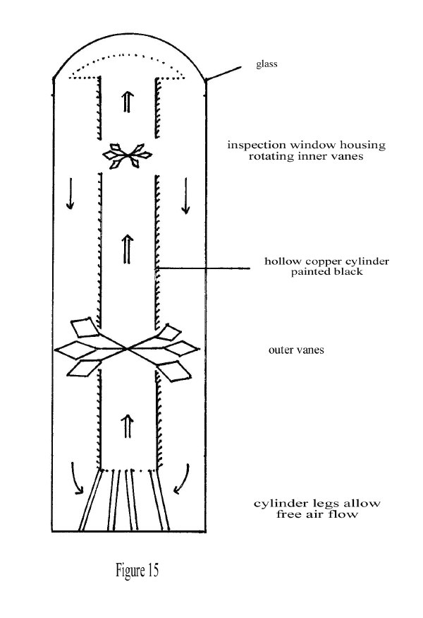
Whilst on a visit to the Science Museum in London to see their excellent collection of Crookes Radiometers and Otheoscopes, I was first immediately drawn to a neighbouring display case. The Convection Mill was invented by A R Bennett1 (Figure 15). It is described variously as ‘Solar energy, utilising’ and as an ‘improved differential air motor’2. The model on display in the Science Museum was built in 1919 to demonstrate the phenomenon of convection currents. It consists of a hollow central upper funnel or chimney, inside which rotates a small light aluminium vane. Below this is a larger vane which revolves in the space surrounding the chimney. The whole is enclosed in a glass case containing air at atmospheric pressure.
On exposing the instrument to sunlight, solar energy is absorbed by the blackened walls of the chimney. A current of warm air passes up the chimney until it reaches the glass shade, where the excess of heat is absorbed and re-radiated outwards. The air cooled in this way falls down to the bottom of the enclosure and the convection currents thus generated, upwards inside the chimney and downwards in the space outside it, cause the two sets of vanes to rotate in opposite directions.
The above notes have been compiled from the Science Museum Library description3. There is no attempt to harness the rotational energy and no comment on its efficiency but the Convection Mill illustrates accurately the forces at work in the proposals outlined in this paper. It again operates in a constant volume closed cycle.
1
British Patent Specification No. 8,711 (1896) A R Bennett.2
Hot Air Caloric and Stirling Engines by Robert Sier, L A Mair 1999, 48-9.3
Science Museum Description Catalogue, Part II Heat and Cold, 1954, 27.