Solar Electricity Using Convection Currents in a Constant Volume Closed Cycle
All heat engines involve extraction of work during the expansion of a gas. A large amount of energy is lost in the combustion products or to an energy sink during the compression stage of the cycle. The maximum efficiency is given by Carnot’s theorem as D T/T.
In complete contrast the proposals outlined in this paper involve energy cycles at constant volume. Energy is absorbed by, and work is extracted from a flow of gas at constant external volume. When air is heated it expands and rises and when it does work, it cools, contracts and falls. Gravity drives convection currents in a constant volume apparatus. Since no energy is lost in exhaust gases or to an energy sink, the conversion efficiency might approach a theoretical or hypothetical 100 per cent.
Consider the following configuration:

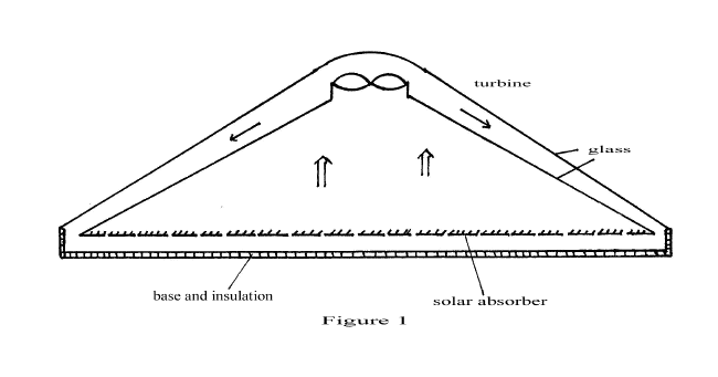
Figure 1 depicts a circular solar panel with two layers of high transmittance, low emissivity glass. The solar absorber is abundantly perforated with up to 10% of its area of holes/interstices to allow the upward flow of air. The base is well insulated. The solar panel is sealed and contains air at atmospheric pressure. The turbine could be any wind energy turbine with its vanes rotating horizontally. A Wells turbine is preferred for its high efficiency in a cased volume and because it has the unusual property of rotation in the same direction for any downflow reflected by the dome.
Solar energy passes through the glass and is taken up by the absorber with >90% efficiency. Air molecules strike the absorber surface, are warmed and rise. A convection current will be set up where rising warm air is channelled into the turbine by the lower layer of glass. As the air current flows through the turbine it surrenders its energy with high efficiency causing rotation and producing electricity. Post turbine, the cooled air is heavier and will descend between the two layers of glass to the base of the panel to complete the cycle.
It is my assertion that solar energy will be converted into electricity with an efficiency of up to 100% in this apparatus. Should efficiency be significantly below this, cooling would be necessary to take away surplus heat. This could be achieved by having an uninsulated metallic base, a base raised above ground for ambient air cooling or by water cooling of the base.
The Simple Solar Engine described could be of 1-10 metres diameter, of height 1-5 metres and with a swept turbine area 1-10% that of the solar absorber. A solar farm could be constructed of rows of such units. Alternatively the triangular cross-section shown could be built in a cloche arrangement with units of up to 100 metres length, 10 metres width, 5 metres height with turbines at regular intervals along the length. Solar farms could be built of parallel rows of such cloches. In tropical climates with insolation of 6 KWH/square metre/day a 1 square kilometre solar farm would have an average output of 250 Megawatts if there if efficient conversion of solar energy into electricity.

A wide variety of different configurations can be devised based on the above principles. Figure 2 depicts a circular SSE which could be of 1 metre diameter using a conventional wind turbine to extract energy from the entire area. The base is painted with solar absorber. Solar energy heats the absorber. As air molecules collide with the absorber surface, they take up heat and rise. There is an upward current of warm air. As these molecules strike the vanes of the turbine they surrender their energy which is converted efficiently into electricity. The cooler molecules then fall to the base to repeat the cycle.
Figures 3 and 4 depict a SSE that could be fitted against the South-facing wall of a building. The solar absorber is of solid continuous material (NOT perforated) and of the same width as the panel. As solar energy is absorbed, warm air rises driving the turbine and drawing cooler air to replace from behind the absorber. Indeed the fact that as warm air rises it draws in cooler air to replace should mean that the turbine could be placed at ground level as in Figure 4.
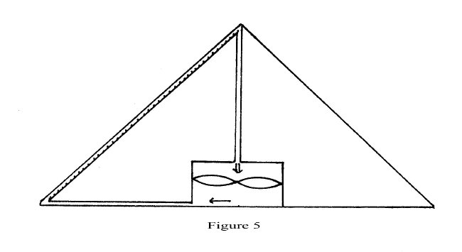
The SSE could be adopted for roof solar electricity as shown in Figure 5. The solar air collector is placed on the roof with the convection currents generated driving a Wells turbine sited in the attic in a sealed system.
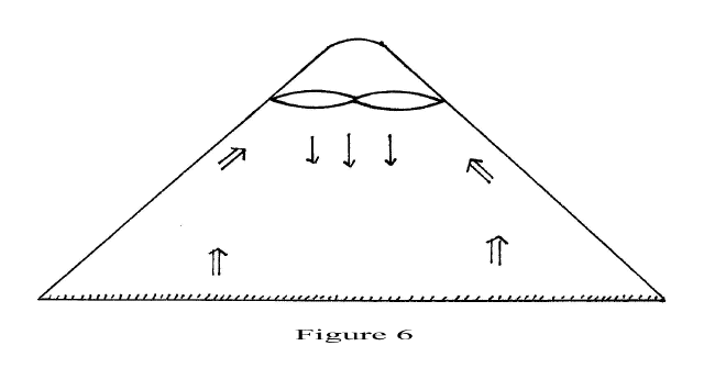
If cased turbines can be devised that are highly efficient and if waste heat is not a problem then the simplest solar engine could be as in Figure 6. Hot air rises from the ground level solid solar absorber in this sealed system. The warm air is directed by the sloping glass sides to the Wells turbine. The warm air stream rotates the turbine surrendering its energy and descends. If some of the hot air rises above turbine level it is reflected by the dome and as it strikes the turbine from above will again cause rotation in the same direction. The configuration shown could be circular or being of this triangular cross-section could form a cloche. A solar farm could be built of such units as described for Figure 1.
Figures 7, 8, 9 and 10 represent possible configurations for a large scale solar air collector. The area under glass would be of the order of one square kilometre with the entire volume securely sealed. The solar absorber in Figures 7-9 is abundantly perforated with up to 10% of its area of holes/interstices to allow the upward flow of air. In Figure 7 the turbine could be placed at (1), (2) or (3). The solar air collector is effectively a massive generator of warm air wind. As the warm air passes through the turbine it does work, it cools and continues its cycle. In Figure 8 the Wells turbine is symmetrically placed between warm air and cool air. It is envisaged that the vertical height involved would be 10-30 metres giving an elevation of 1-3%. Figure 9 depicts a turbine of larger proportions to provide elevation of up to 10° . If elevation is a problem then the SSE could be built on a South-facing hillside as depicted in Figure 10. This may provide 10-30% elevation and necessitate construction of vertical and horizontal shafts to carry the air currents. In that case the turbine could be constructed at sites 1, 2, 3 or perhaps most conveniently site 4 in the Figure.
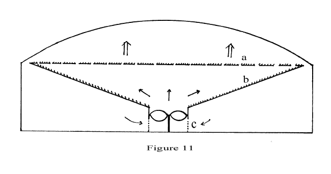
Figure 11 describes a SSE with maximum absorption surface for solar energy and where the Wells turbine is more conveniently sited at ground level. The solar absorber a is abundantly perforated with up to 10% of its area of holes/interstices. The sloping sides b are of solid continuous surface and coated with absorber paint to collect solar energy that will have passed through the interstices in a. The sketch depicts a circular structure with the sides of the cylinder c housing the turbine perforated below turbine level to allow inflow of air.
Solar energy is efficiently absorbed by a and b. This creates an upward current of warm air which draws replacement air through the turbine. Convection currents are set up where all the air that passes through the absorber a must travel through the turbine. This effectively converts the kinetic energy in the warm air wind into electricity.
As with earlier configurations, the above structure could be circular of diameter up to 10 metres and height 1-2 metres. A solar farm could be made up of thousands of these units in regular array. Alternatively Figure 11 could be considered the cross-section of a cloche arrangement which could be 100 metres long and 10 metres wide with turbines at regular intervals. A continuous array over length and breadth for dimensions of 1 kilometre or more could also be set up as in Figure 12.
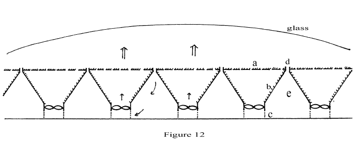
As earlier, a represents the solar absorber with up to 10% perforations, b the solid sloping sides, c the turbine chamber with openings/holes below turbine level to allow air flow and d downpipes to allow air to be drawn from the surface. It is envisaged that the area swept by turbines need only be 1-4% of the solar collector area.
The configuration shown would allow maximum absorption of incident solar energy and convenient ground level location of turbines. The solar farm could be many square kilometres in area but need be no more than 10 metres high. The available volume e could be partly filled with an energy storage material eg thermal brick, stone, rock pile … where at night, convection currents would be reversed to provide night electricity.
Carrier gas pressure
In every variation described of the SSE it is assumed that the carrier gas would be air at atmospheric pressure. This would be for reasons of convenience, leakage, maintenance … Since the apparatus is sealed, nitrogen, carbon dioxide or the inert gases could be used to minimise corrosion and extend the lifetime of equipment.
There may be great advantage also in the carrier gas being at low pressure. Calculations based on the kinetic theory of gases and the dimensions of the particular SSE indicate that a pressure of 10-2 or 10-3 atmospheres may be adequate for efficient energy transport. Use of such lower pressure would reduce heat losses through the glass of the solar collector.